Other Inner Planets

The inner solar system, composed of Mercury, Venus,
and Mars (besides Earth),
has generally presented an easier target for study than the far-off outer
planets. Within the last ten years, Mars, especially, has been the most
intriguing target for study. So far this century has only seen missions
on Mars, both by NASA and the ESA. These include 2001 Mars Odyssey, Mars
Express, and Mars Exploration Rovers. Additionally, NASA's Mars Reconnaissance
Orbiter has been launched and it should reach Mars in 2006.
Two additional missions that have been launched but
not yet reached their targets are NASA's MESSENGER mission to Mercury
which should reach the planet in 2011, and ESA's Venus Express mission
to Venus that should reach the planet in 2006.
 The
2001 Mars Odyssey was originally called the Mars Surveyor 2001 Project,
and was to consist of both a lander and an orbiter. However, due to cut-backs
and reorganization, the lander was abandoned and the orbiter set as the
only part of the project. The
2001 Mars Odyssey was originally called the Mars Surveyor 2001 Project,
and was to consist of both a lander and an orbiter. However, due to cut-backs
and reorganization, the lander was abandoned and the orbiter set as the
only part of the project.
The orbiter is designed to orbit Mars for over five
years and to collect data for three of those. The probe is designed to
take measurements on Mars' mineral content and atmosphere / environment.
One of the main objectives for this project is to attempt to determine
if Mars ever had a suitable environment for life to
develop. Other objectives are to learn about the climate and geology
of Mars, as well as to determine any potential radiation hazards to potential
astronaut visitors.
2001 Mars Odyssey was launched on April 7, 2001. After
seven months, it reached Mars on October 23, 2001. Over the next three
months, it used the Martian atmosphere to aerobrake, and to finally assume
a standard orbit on January 30, 2002, of approximately 400 km (250 mile)
altitude. It orbits the planet now every two hours.
Besides its primary science objectives, the 2001 Mars
Odyssey will also be used as a relay station for rovers that will be
sent to Mars later this year (2003), and possibly other probes as well.
Even though its 917-day mission ended in July of 2004, NASA extended
the mission an additional Martian year through September 2006. Afterwards,
if the craft is still working, NASA plans on continuing to use the probe
as a relay station for communications with other probes in orbit and
on the surface.
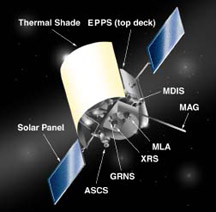
Neutron Spectrometer (NS):
- This is designed to detect hydrogen on the surface of Mars to a depth
of about 1 m. This data will be used to characterize the abundance
and distribution of water on Mars. The NS detects neutrons in three
energy ranges: thermal, epithermal, and fast.
- The detector is a rectangular block which is divided internally into
4 prisms, one which faces downward towards the planet, or nadir, one
faces upward, away from the planet (zenith), one faces into the spacecraft
(aft), and one faces out in the direction of the spacecraft velocity
(forward). Each prism is a boron-loaded plastic scintillator, optically
isolated from the other prisms. Each prism is viewed by a separate
photomultiplier tube.
- When an energetic particle strikes the scintillator, a flash of light
results which is detected by the photomultiplier tube. The small ends
of the box are covered by a thick sheet of cadmium which is an effective
shield against neutrons. The downward looking prism also has a cadmium
shield so only neutrons above a certain energy can enter.
- Thermal neutrons are low-energy, slow-moving, cosmic-ray generated
neutrons which have lost much of their energy in collisions with hydrogen
atoms. They are scooped up by the forward prism but outrun by the aft
prism. The difference in counting rates between these prisms gives
a measure of the thermal neutron flux. The difference in rates between
the aft prism and zenith prism gives a fractional measure of epithermal
neutrons. The aft prism also measures spacecraft-generated neutrons.
Epithermal neutrons are also measured by the shielded nadir prism.
The ratio of thermal to epithermal neutrons gives an indication of
the amount of hydrogen present in the ground.
High Energy Neutron Detector (HEND):
- This is designed to measure the flux of neutrons at different energies.
This data will be used to determine neutron albedo parameters for use
in interpretation of the gamma-ray data and to construct a global map
of regions with subsurface water or ice. The ratio of slow to fast
neutrons gives an indication of the abundance of hydrogen at the surface
(because collisions with hydrogen atoms slows neutrons down) and this
can be used to estimate the abundance of water.
- HEND is composed of three proportional counter detectors based on
Helium-3 LND 2517 counters and polyethylene moderators with cadmium
shields: A small detector with a thin moderator for detecting neutrons
of energy 0.4 to 10 eV, a medium detector with a thicker moderator
(10 eV to 1 keV), and a large detector with a thick moderator (1 keV
to 1 MeV). There is an internal scintillation sensor which uses a Stilben
crystal and photomultiplier tube (PMT) to detect high energy (300 keV
to 10 MeV) neutrons and gamma ray photons from 60 keV to 1 MeV, and
an external scintillation sensor using a CsI crystal and PMT for detection
of protons with energies above 300 keV and hard X-rays above 30 keV
for anti-coincidence rejection.
Thermal Emission Imaging System (THEMIS):
- This instrument consists of a thermal infrared imaging spectrometer
and a high-resolution camera which will be used to map the mineralogy
and morphology of the surface of Mars. Specifically, THEMIS will be
used to characterize localized deposits associated with hydrothermal
or sub-aqueous environments, to identify potential sample return sites,
to study small-scale geologic processes, and to search for temperature
anomalies associated with active subsurface thermal systems, if any
exist.
- The THEMIS instrument is 54.5x37.0x28.6 cm in size and is mounted
on the spacecraft science deck. It uses an all-reflective, three-mirror
f/1.7 anastigmatic telescope with an effective aperture of 12 cm and
an effective focal length of 20 cm to focus light onto the infrared
and visible detectors via a dichroic beam splitter. The infrared imager
detector is a 320 x 240 micro-bolometer array with a field of view
of 4.6° crosstrack by 3.5° downtrack. The array temperature
will be stabilized by a thermal electric cooler. The filters are mounted
directly over the focal plane. The instrument will detect emitted infrared
radiance in nine filtered bands between 6.6-15.0 µm. These filter
bands are centered at (with full-width half-power bandwidth) in micrometers:
6.62 (1.01), 7.88 (1.09), 8.56 (1.18), 9.30 (1.18), 10.11 (1.10), 11.03
(1.19), 11.78 (1.07), 12.58 (0.81), 14.96 (0.86). The spectrum will
include contributions from the atmosphere as well as the surface. The
thermal infrared imaging spectrometer will map the entire planet at
a resolution of 100 m per pixel.
- The visible imager consists of a 1024 x 1024 silicon array with a
2.9° square field of view. The visible camera will have a resolution
of 18 meters per pixel in 5 wavelength color bands centered at 0.423,
0.553, 0.652, 0.751, and 0.870 µm with a bandwidth (full-width
half-power) of 0.05 µm. The five stripe filters are mounted directly
on the detector. The entire detector array will be read out every 1.3
seconds. Up to 15,000 panchromatic visible images will be returned.
The infrared and visible images will be co-aligned.
Gamma Ray Spectrometer (GRS):
- This is used to monitor the gamma rays emitted from the surface of
Mars at different energies and from the energy spectrum determine the
elements present at the martian surface. These measurements will be
used to determine the elemental abundances of the martian surface material
including composition of the permanent polar caps, to map the distribution
of water and to determine its near-surface stratigraphy, and to determine
the thickness of the seasonal polar caps and their variation with time.
The instrument will also be used to study the nature of cosmic gamma-ray
bursts.
- The GRS is an emission spectrometer consisting of a 1.2 kg high-purity
germanium diode as a solid-state detector. The diode is reverse biased
to ~3000 volts and has leakage currents <1 nA. Current produced
by gamma rays in the diode are amplified by a low temperature pre-amplifier.
A radiative cooler covered by a hatch is used to cool the sensor below
90 K. The sensor is surrounded by a thermal shield so it can be heated
to 100 C before the orbital measurements to anneal any radiation damage
occurring during the cruise phase.
- The GRS is mounted at the end of a six-meter boom to minimize interference
from gamma-rays emitted by the spacecraft. The instrument is bowl shaped,
46 cm in diameter at its widest point, the radiator cover at the top
of the sensor, and 17 cm high. The detector is nadir-pointed and has
a field of view of 144°. The spatial resolution of the GRS is about
300 km, but lower resolution will be necessary for elements with lower
count rates. Long integration times will be used to build up spectra
which can be interpreted in terms of element abundances.
- The instrument will also be equipped with two neutron detector systems
to detect hydrogen. One neutron detector will measure thermal, epithermal,
and fast neutrons, the other will primarily measure fast neutrons.
Mars Radiation Environment Experiment (MARIE):
- This is an energetic particle spectrometer designed to measure the
near space radiation environment as related to the radiation hazard
to human explorers. Specifically, MARIE will determine the energy deposition
spectrum from 0.1 keV/µm to 1500 keV/µm, separate the contribution
of proton, neutrons, and HZE particles, measure the accumulated absorbed
dose and dose rate which would occur in tissue, and determine the radiation
quality factor.
- The spectrometer consists of two 24x24 position sensitive detectors
(each roughly 2.5x2.5 cm in size) and two 2.5x2.5 cm silicon detectors.
These are backed by two 1.78x1.78 cm proportional counters, one total
energy proportional counter (TEPC) and one charged proportional counter
(CPC). There are two 0.9 µCurie alpha sources and two 40 torr
propane vessels. Data is saved on 60 Mb of flash memory and transferred
at <8 Mbits per day over an RS-422 low speed data line. The entire
unit is 10.2 cm x 17.8x29.2 cm. The field of view is 56° and energy
is measured in 512 channels covering the 0.1 to 1500 keV/µm range.
- During the cruise to Mars, in August, the MARIE instrument failed
to respond during a routine data transfer and was put into hibernation.
Attempts to revive the instrument were successful in March 2002 and
MARIE began taking scientific data from orbit on March 13.
|
| Launch Date |
April 7, 2001 at 15:02:22 UTC |
| Mass |
376.3 kg plus 348.7 kg of fuel at launch |
| Dimensions |
2.2x1.7x2.6 m |
| Power Output |
gallium arsenide solar cells in the solar panel and
a 16 A-hr nickel hydrogen battery |
| Propulsion |
hydrazine and nitrogen tetroxide rocket which can produce
65.3 kg of thrust |
| Stabilization |
three-axis stabilized using three primary reaction
wheels and one backup |
| Communication |
X-band high-gain antenna for Earth-Mars; UHF antenna
for Mars-Mars |
| Computer |
RAD6000 computer with 128 MB RAM and 3 MB of non-volatile
memory |
|
| Experiments: |
Name |
Mass (kg) |
Power Consumption (W) |
Principal Investigator |
| Neutron Spectrometer (NS) |
|
|
Dr. William C. Feldman |
| High Energy Neutron Detector (HEND) |
3.7 |
5.7 |
Dr. Igor G. Mitrofanov |
| Thermal Emission Imaging System (THEMIS) |
11.2 |
14 |
Prof. Philip R. Christensen |
| Gamma-Ray Spectrometer (GRS) |
30.5 |
32 |
Dr. William V. Boynton |
| Mars Radiation Environment Experiment (MARIE) |
3.3 |
7 |
Mr. Gautam Badhwar, III |
This consists of an orbiter, Mars Express Orbiter, and
a lander, Beagle 2. The purpose of the orbiter is to take global high-resolution
photography (10 m (33 foot) resolution), mineralogical mapping (100 m
(330 foot) resolution) and mapping of the atmospheric composition, study
the subsurface structure, global atmospheric circulation, interaction
between the atmosphere and the subsurface, and the atmosphere and interplanetary
composition. The Beagle 2 lander is supposed to characterize the landing
site geology, mineralogy, and geochemistry, the physical properties of
the atmosphere and surface layers, collect data on the meteorology and
climatology, and to search for possible signatures of life.
 The
craft was launched on June 2, 2003. It reached Mars on December 26, 2003,
but the lander was released on December 21, 2003. The orbiter entered
into a highly elliptical orbit, which, after a few days, was altered
into a polar orbit that will eventually settle into a 250x11,583 km (155x7200
mile) orbit at 86° of 6.7 hours. This will begin the main mission,
and it will last approximately 440 days. Then, the orbit will be modified
so that the farthest point will be at 10,243 km (6365 miles) above the
surface. The total orbiter mission is planned to last one Martian year
- approximately 687 days. The
craft was launched on June 2, 2003. It reached Mars on December 26, 2003,
but the lander was released on December 21, 2003. The orbiter entered
into a highly elliptical orbit, which, after a few days, was altered
into a polar orbit that will eventually settle into a 250x11,583 km (155x7200
mile) orbit at 86° of 6.7 hours. This will begin the main mission,
and it will last approximately 440 days. Then, the orbit will be modified
so that the farthest point will be at 10,243 km (6365 miles) above the
surface. The total orbiter mission is planned to last one Martian year
- approximately 687 days.
The Mars Express radar system (MARSIS) was deployed
between May 2 and June 19, 2005. It was commissioned over the next few
weeks, and it began its first science observations in August 2005.
The Beagle 2 entered the atmosphere on December 26,
2003, and released parachutes when it was approximately 1 km (0.62 miles)
above the surface. The Beagle 2 lander was declared lost on February
6, 2004, after it had not contacted any orbiting craft nor receiver on
Earth.
What was supposed to happen was large gas bags were
to inflate around the lander to protect it when it hit the surface. After
landing, the bags would deflate and the top of the lander will open to
expose four solar array disks. Within the body of the lander, an antenna
would have been deployed and the lander arm released. The lander arm
would have dug up samples to be deposited in the various instruments
for study; the "mole" was to be deployed, crawling across the
surface at a rate of about 10 cm (4 inches) per minute and capable of
burrowing under rocks to collect soil samples for a gas analysis system.
The Beagle 2 cost roughly 40 million British pounds
($57 to $65 million U.S.) The overall Mars Express budget excluding the
lander is 150 million Euros (~$150 million U.S.).
High-Resolution Stereoscopic Camera (HRSC):
- This is designed to provide color stereo imaging at multiple phase
angles at high resolution and to provide global coverage of Mars. The
camera is a push-broom scanning device with 9 CCD's.
- Scientific objectives are to characterize surface morphology, topography,
and geological evolution, to identify geologic units, to help refine
the geodetic control network, and to analyze atmospheric phenomena
including climatology, the role of water, and surface/atmosphere interactions.
- HRSC is derived from the Russian Mars-96 mission.
Infrared Mineralogical Mapping Spectrometer, or Observatoire pour la
Mineralogie, l'Eau, les Glaces et l'Activit (OMEGA):
- This is a visible and near-infrared mapping spectrometer designed
to provide global data on the mineralogical and molecular composition
of the martian surface at medium resolution. The instrument will spectrally
analyzed re-diffused solar light and surface thermal emission.
- The scientific objectives are to characterize the composition of
surface material and monitor atmospheric dust.
- The OMEGA instrument is derived from the Russian Mars-96 mission.
Atmospheric Fourier Spectrometer, or Planetary Fourier Spectrometer
(PFS):
- This is a Fourier infrared spectrometer designed for atmospheric
studies. It has two channels, one with a 10 km footprint and one with
20 km.
- The scientific objectives are to return three-dimensional temperature-field
measurements of the atmosphere up to 50 km altitude, constituent variations
(water and carbon dioxide), and the optical properties of atmospheric
aerosols, which will allow the study of global atmospheric circulation,
and data on the thermal inertia of the martian surface.
- The PFS instrument is derived from the Russian Mars-96 mission.
Ultraviolet and Infrared Atmospheric Spectrometer, or Spectroscopic
Investigation of the Characteristics of the Atmosphere of Mars (SPICAM-UV):
- This is designed to study the atmosphere with nadir- and limb-viewing
modes. It will measure the ozone content of the atmosphere, the coupling
of ozone and molecular hydrogen, and vertical profiles of carbon dioxide,
ozone, and dust (using stellar occultation techniques).
- This data will be used to constrain meteorological and dynamic models
of Mars' atmosphere.
- The SPICAM-UV instrument is derived from the Russian Mars-96 mission.
Subsurface Sounding Radar/Altimeter, or Mars Advanced Radar for Subsurface
and Ionospheric Sounding (MARSIS):
- This is a multi-frequency nadir-looking instrument which will employ
two 20 m antennas, which form a 40 m dipole oriented perpendicular
to the flight and nadir directions, to characterize the subsurface
structure of Mars to a depth of a few kilometers, provide altimetry
and roughness data, and make ionospheric measurements.
- The primary scientific objectives are to map the distribution of
liquid water and ice, for studies of Mars' geologic, climatic, and
possibly organic evolution.
Energetic Neutral Ions Analyzer, or Analyzer of Space Plasmas and EneRgetic
Atoms (ASPERA):
- This consists of a neutral particle imager and ion spectrometer mounted
to a scanning platform.
- Its primary scientific objective is to measure the plasma-induced
atmospheric escape and the interaction of the solar wind with the martian
ionosphere.
Mars Radio Science Experiment (MaRS):
- This will utilize the Mars Express orbiter radio subsystem to characterize
dielectric properties of the surface, the martian gravity field, and
the neutral and ionized atmosphere (by sounding at occultations).
Lander Communications Relay (MARESS) will be used to communicate with
the Beagle 2 lander on the martian surface.
|
| Launch Date |
June 2, 2003 at 17:45 UTC |
| Launch Vehicle |
Soyuz/Fregat from Baikonur Cosmodrome |
| Mass |
1123 kg launch mass included 666 kg main mus, 113 kg
payload, 60 kg lander, and 457 kg of propellant |
| Dimensions |
1.5x1.8x1.4 m; solar panels measure 12 m total; 1.8
m diameter antenna |
| Power Output |
660 W |
| Propulsion |
bi-propellant 400 N main engine; two 267-liter propellant
tanks have a total capacity of 595 kg (~370 kg are needed for the
nominal mission); pressurized He from a 35 liter tank is used to
force fuel into the engine; trajectory corrections will be made using
a set of eight 10 N thrusters, one attached to each corner of the
spacecraft bus |
| Stabilization |
three-axis stabilization by two 3-axis inertial measurement
units, a set of two star cameras and two Sun sensors, gyroscopes,
accelerometers, and four 12-Nms reaction wheels |
| Communication |
X-band (7.1 GHz) and S-band (2.1 GHz) uplink and downlink;
two Mars lander relay UHF antennas are mounted on the top face for
communication with Beagle 2 |
| Computer |
two Control and Data management Units with a 10 gigabit
solid state mass memory for storage of data and housekeeping information
for transmission |
|
| Experiments: |
Name |
Mass (kg) |
Power Consumption (W) |
Principal Investigator |
| Super / High-Resolution Stereo Color Imager (HRSC) |
|
|
Dr. Gerhard Neukum |
| Infrared Mineralogical Mapping Spectrometer (OMEGA) |
|
|
Dr. Jean-Pierre Bibring |
| Atmospheric Fourier Spectrometer (PFS) |
|
|
Dr. Vittorio Formisano |
| Ultraviolet and Infrared Atmospheric Spectrometer (SPICAM-UV) |
|
|
Dr. Jean-Louis C. Bertaux |
| Subsurface Sounding Radar / Altimeter (MARSIS |
|
|
Dr. Giovanni Picardi |
| Energetic Neutral Ions Analyzer (ASPERA) |
|
|
Prof. Rickard Lundin |
| Radio Science Experiment (MaRS) |
|
|
Dr. Martin Paetzold |
| Lander Communications Relay (MARESS) |
|
|
Dr. Enrico Flamini |
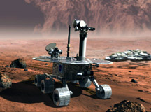
This program is another that plans on landing on Mars.
It is designed to take panoramic pictures, search for evidence of past
or present water, and perform other experiments on rocks. Scientists
from Earth will be able to command the vehicles to specific areas of
interest.
It consists of two rovers that are based upon that used
in the Mars Pathfinder mission.
The first was launched on June 10, 2003, and it landed on January 3,
2004 (GMT). The second rover was launched on July 7, 2003 at 23:18:15
EDT, and it landed on January 25, 2004 at 5:05 GMT.
The rovers are designed to travel approximately 100
m (330 feet) each martian day (24 hours and 37 minutes). Each rover's
primary mission lasted for approximately 90 Martian (92 Earth) days.
However, they have been successfully operating for nearly a full Martian
year, and they have had their missions extended until at least November,
2006, assuming they continue to operate. For more up-to-date information,
see the Current Events, and for information
on what the craft have discovered, see the Mars page.
Panoramic Camera (Pancam):
- This is a pair of high-resolution CCD imagers mounted on the Pancam
Mast Assembly. The imagers are side-by-side on a "camera bar" to
allow stereo imaging. They are separated by 30 cm horizontally and
have a 1° toe-in, giving stereo coverage from roughly 5-100 m.
Each camera's optics consists of a protective sapphire window and 3-element
symmetrical lenses with an effective focal length of 38 mm and a focal
ratio of f/20, giving a field of view of 16.8°x16.8°, or 0.28
mrad/pixel. Optimal focus is from 1.5 m to infinity.
- Each camera has an eight position filter wheel giving multispectral
imaging capability in the 400-1100 nm range. The left camera has one
clear filter and a set of filters at: 750 nm (±20 nm range),
670 (20), 600 (20), 530 (20), 480 (25), 430 (short-pass filter), and
a 440 nm solar filter. The right camera filters are 430 (short-pass),
750 (20), 800 (20), 860 (25), 900 (25), 930 (30), 980 (long-pass),
and an 880 nm solar filter.
- The mast can rotate 360° to give full panoramic views and the
camera bar can swing up and down 180°, with pointing control better
than 2° in azimuth and 1° in elevation. The mast holds the
camera about 1.3 m above the surface. Images are 12-bit, captured on
a 1024x2048 pixel Mitel CCD array, one 1024x1024 pixel region constituting
the active imaging area and the other 1024x1024 pixels acting as a
frame transfer buffer. Mosaics as large as 4000x24000 pixels can be
generated. Exposure times up to 30 sec are possible. Signal to noise
ratio is greater than 200. A target is carried on the rover for calibration
of the cameras during the mission. There is also a vertical post to
cast a shadow on parts of the target during calibration.
Microscopic Imager (MI):
- This is designed to take highly magnified close-ups of martian rocks
and soils. The instrument consists of a microscope and a CCD camera
mounted on the rover arm, or instrument deployment device, which can
position the imager against its target. The field of view is 1024x1024
pixels and there is a single broad-band filter with a spectral bandpass
of 400-680 nm. The optics use a fixed focus design at f/15 that gives ±3
mm depth-of-field. The focal length is 20 mm and the working distance
is 63 mm from the front of the lens barrel to the object plane. Resolution
is 30 µm/pixel and the field of view is 31x31 mm. The CCD array
is 1024x1024 pixels.
- Ambient sunlight will be used to illuminate target surfaces. Movement
of the MI between successive images will enable stereoscopic viewing
and production of mosaics that are well focused across the entire frame.
The MI will be used to analyze the size and shape of grains in sedimentary
rocks to help determine if liquid water was present in the past.
Miniature Thermal Emission Spectrometer (Mini-TES):
- This is a compact infrared spectrometer designed to determine the
mineralogy of rocks and soils from a distance by measuring their patterns
of thermal radiation. It will also take spectra from the atmosphere
of Mars to provide information on dust, water vapor, and temperature.
Mini-TES is located in the body of the rover at the base of the Pancam
Mast Assembly. The Pancam Mast holds a viewing port with a scan mirror
at the same level as the Panoramic Camera assembly, 1.3 m above the
ground. Light goes through the viewing port, reflects off the scan
mirror and enters the mast, which is built like a periscope, reflecting
the light down to a telescope at the base of the mast and on to the
spectrometer.
- Mini-TES is based on a Michelson interferometer design which covers
the wavelength range from 5-29 µm (2000-345 cm-1) with a scan
resolution of 10 cm-1. The field of view can be alternated between
8 and 20 mrad. The mast can turn a full 360° and the scan mirror
ranges from -50° to +30° in elevation. These are sequenced
to provide a raster image of the scene. The telescope at the base of
the mast is a reflecting Cassegrain with a 6.35 cm mirror and a focal
ratio of f/12.
- The approximately collimated beam is fed from the telescope to the
980-nm interferometer which generates interference fringes. The instrument
uses a single un-cooled deuterated triglycine pyroelectric detector.
A signal-to-noise ratio of 450 or better will result from co-addition
of two observations. An internal (inside the head of the Pancam Mast
Assembly) and external (on the rover deck) targets are also available
to provide calibration between or during image scans. The mini-TES
will operate primarily during mid-day (between 10 A.M. and 3 P.M. local
time), but may also operate at night to obtain diurnal cycle temperature
information.
Mossbauer Spectrometer (MB):
- This is designed specifically to study iron-bearing minerals. The
sensor head for the MB is mounted on the end of the rover arm, or instrument
deployment device. The arm can place the sensor head directly on a
sample to be studied. A single measurement takes about 12 hours. The
electronics board for the MB, with a mass of about 0.14 kg and a volume
of 16x10x2.5 cm is contained in the warm electronics box in the body
of the rover. The MB was built by the Mossbauer Group at Johannes Gutenberg
University.
- The sensor head has a mass of about 0.41 kg and a volume of about
9.0x5.0x4.0 cm and contains a 57Co/Rh source to illuminate the target.
The source is moved at a known velocity by a Mossbauer drive and backscattered
radiation is measured by gamma- and x-ray detectors in the sensor head.
The gamma signals are binned by source velocity. The mineralogical
information on the target is given by hyperfine splitting of 57Fe nuclear
levels. There are five analog detector channels which are analyzed
by discriminators for 14.41 keV and 6.4 keV peaks.
- Mossbauer spectra for the two energies are sampled separately, each
consisting of 512 x 3-byte integers. Calibration spectra will be taken
during sampling using a reference channel in the instrument. A magnetite-rich
calibration target will also be mounted on the rover where it can be
directly viewed by the MB. The 12-hour measurement run will be timed
to include daytime maxima and nighttime minima temperatures to use
the temperature dependent behavior of the Mossbauer parameters to help
determine the nature of the iron-bearing phases.
Alpha Particle X-ray Spectrometer (APXS):
- This is designed to determine the elemental chemistry of rocks and
soils on the surface of Mars. The APXS sensor head is mounted on the
rover arm, or instrument deployment device, and is operated by placing
the sensor directly on the sample. The APXS works by exposing the target
to energetic alpha particles and X-rays emitted by a radioactive 244Cm
source in the sensor head and measuring the energy spectrum of backscattered
alpha particles and emitted X-rays from the target. Using this technique
abundances of all rock-forming elements except hydrogen can be measured.
- The APXS sensor head contains six 244Cm sources with a total source
strength of 30 mCi. Each source is covered with 3 µm aluminum
foils that reduce the energy of the emitted alpha particles from 5.8
MeV to 5.2 Mev, which serves to suppress the atmospheric carbon dioxide
background. Collimators in front of the sources give a field of view
38 mm in diameter at 29 mm working distance. Six alpha detectors surround
the source and inside these is a high-resolution silicon drift X-ray
detector. A pair of doors protects the sensor from martian dust. When
the sensor head is put in place, the doors swing open to expose the
source and detectors. The instrument electronics are housed in the
warm electronics box.
- The X-ray detector can measure major elements such as Mg, Al, Si,
K, Ca, and Fe and minor elements including Na, P, S, Cl, Ti, Cr, and
Mn. The FWHM of the x-ray detector is 160 eV at 6.4 keV. The alpha
detector is better suited for lighter elements, particularly C and
O. FWHM for detections at 5.8 MeV is less than 100 keV. The detection
limit is about 0.5 to 1 weight percent. The time for a full measurement
is at least 10 hours. The x-ray mode alone takes significantly less
time than this. Most data accumulation is planned for nighttime when
temperatures are lowest, giving the best spectral resolution.
Rock Abrasion Tool (RAT):
- This is a device containing a grinding wheel designed to remove dust
and weathered material from the surface of a rock to expose a fresh
surface. The fresh surface, which is more likely to represent the original
rock before alteration, can then be studied by the other rover instruments.
It is mounted on the rover arm, or instrument deployment device and
is placed by the arm against the target rock.
- The RAT is 7 cm in diameter and 10 cm long. It uses two diamond matrix
wheels. Each wheel has two teeth which cut out a circular area as the
head rotates at high speed. The grinding wheels can also slowly revolve
around each other, sweeping the two circular areas over a 4.5 cm diameter
cutting region. The wheels can penetrate by fractions of a mm as commanded,
creating a hole as deep as 0.5 cm. Penetration into the rock is slow
and designed to minimize alteration of the petrologic fabric, chemistry,
or mineralogy. Currents and temperatures will be monitored during the
grinding operation to infer information on the rock properties. Grinding
operations take about 2 hours for a dense basalt.
Magnet Arrays:
- This experiment is designed to gather samples of the magnetic components
of martian dust, soil, and rocks to determine their mineralogy and
origins. The types of magnetic minerals present on Mars may reveal
information on past conditions on the planet.
- There are three Magnet Arrays on each Mars Exploration Rover.
- One array is mounted on the RAT on the rover arm to collect samples
of dust produced during the grinding process. This array consists
of four magnets of different strengths, each 0.7 cm in diameter
and 0.9 cm thick. The different strengths will allow a range of
magnetic materials to be captured and examined by the Panoramic
Camera. After examination, the magnets are designed with a temperature-driven
retraction device, which slides the magnets into a sleeve each
night when temperatures drop, clearing off the magnets for the
next set of samples.
- Another array is mounted on the front of the rover at an angle
so that non-magnetic particles will fall off and only magnetic
particles will stick to the array. The samples can then be analyzed
by the Mossbauer spectrometer and APXS. The array consists of one
capture magnet and one filter magnet. The capture magnet is a strong
magnet designed to attract all iron-containing dust while the weaker
filter magnet is designed to capture only the most magnetic dust.
These magnets are each contained within an aluminum disk 4.5 cm
in diameter.
- The third magnet is a sweep magnet mounted on top of the rover
deck in view of the Pancam so the material collected can be imaged
at high resolution. The sweep magnet is a thin-walled magnetic
tube magnetized along its symmetry axis. It is strong enough to
deflect the paths of wind-transported magnetic particles, which
will accumulate in a narrow ring corresponding to the tube. The
central surface inside the ring will collect non-magnetic particles,
and at greater radial distances both magnetic and non-magnetic
particles will accumulate.
Engineering Cameras (Hazcoms and Navcoms):
- There are two types of Engineering Cameras on the Mars Exploration
Rover, the Hazard Avoidance Cameras (Hazcoms) and the Navigation cameras
(Navcoms).
- There are four Hazcoms, two mounted on the lower front of the rover
and two on the lower rear. They are black and white visible light cameras
with a field of view of about 120x120°. The cameras view the terrain
up to 3 m in front of and behind the rover to detect any obstacles
in the path of the rover. The camera output is interperated by software
which directs the rover to avoid any perceived hazards.
- The two Navcams are mounted on the rover mast as a stereo pair. They
take visible light panoramic images with a 45x45° field of view
to assist in navigation of the rover, and also assist the hazard avoidance
imaging by giving a higher perspective of the ground.
|
| Launch Date |
June 10, 2003 at 17:58:47 UT and June 25, 2003 |
| Launch Vehicle |
Delta II 7925 |
| Mass |
185 kg each |
| Power Output |
140 W in full Sun; energy is stored in two rechargeable
batteries |
| Propulsion |
6-wheels; each wheel has its own motor and the two
front and two rear wheels are independently steerable; top speed
is 5 cm/sec; average speed will be 1 cm/sec |
| Stabilization |
can be tilted 45° without tumbling; programmed
to not exceed 30° inclines |
| Communication |
X-band high-gain directional dish antenna and low gain
omni-directional antenna for Earth-Mars; UHF antenna for Mars-Mars |
| Computer |
128 Mb RAM each |
|
| Experiments (each craft carries
all of these): |
Name |
Mass (kg) |
Power Consumption (W) |
Principal Investigator |
| Panoramic Camera (Pancam) |
0.27 |
|
Dr. Steven W. Squyres |
| Microscopic Imager (MI) |
|
|
Dr. Steven W. Squyres |
| Miniature Thermal Emission Spectrometer (Mini-TES) |
2.1 |
|
Dr. Steven W. Squyres |
| Mossbauer Spectrometer (MB) |
0.55 |
2 |
Dr. Steven W. Squyres |
| Alpha Particle X-ray Spectrometer (SPXS) |
|
|
Dr. Steven W. Squyres |
| Rock Abrasion Tool (RAT) |
0.75 |
30 |
|
| Magnet Arrays |
|
|
|
| Engineering Cameras (Hazcoms and Navcoms) |
|
|
|
 No
craft has visited Mercury since Mariner
10 in 1975. Since then, many questions about Mercury have been raised,
and it is hoped that this mission will answer some of them. This mission
is designed to study the characteristics and environment of Mercury from
orbit. Specifically, the objectives are to study the surface composition,
geologic history, core and mantle, magnetic field, tenuous atmosphere,
and to search for water ice and other frozen volatiles at the poles over
a nominal orbital mission of one Earth year
(365 days). No
craft has visited Mercury since Mariner
10 in 1975. Since then, many questions about Mercury have been raised,
and it is hoped that this mission will answer some of them. This mission
is designed to study the characteristics and environment of Mercury from
orbit. Specifically, the objectives are to study the surface composition,
geologic history, core and mantle, magnetic field, tenuous atmosphere,
and to search for water ice and other frozen volatiles at the poles over
a nominal orbital mission of one Earth year
(365 days).
The craft was launched on August 3, 2004, at 6:15:56
UT (2:15:56 A.M. EDT) on a Delta 7925H (a Delta II Heavy launch vehicle
with nine strap-on solid-rocket boosters). The spacecraft was injected
into solar orbit 57 minutes later. The solar panels were then deployed
and the spacecraft began sending data on its status. One year after launch,
on August 2,2005, MESSENGER flew by Earth at an altitude of 2347 km.
On December 12, 2005, at 11:30 UT, MESSENGER fired its large thruster
for 524 seconds, changing the spacecraft velocity by 316 m/s and putting
it on course for its October 24, 2006, Venus flyby at an altitude of
3612 km. There will be another Venus flyby on June 6, 2007, at an altitude
of 300 km.
The first of three Mercury flybys, all at 200 km altitude,
will be on January 15, 2008, the second will be on October 6, 2008, and
the third on September 30, 2009. There will also be five deep space maneuvers.
Data collected during the Mercury flybys will be used to help plan the
scientific campaign during the orbital phase. Mercury orbit insertion
will take place on March 18, 2011, requiring a change in velocity of
0.867 km/s.
The nominal orbit is planned to have a periapsis of
200 km at 60° N latitude, an apoapsis of 15,193 km, a period of 12
hours and an inclination of 80°. The periapsis will slowly rise due
to solar perturbations to over 400 km at the end of 88 days (one Mercury
year) at which point it will be readjusted to a 200 km, 12 hour orbit
via a two burn sequence. Data will be collected from orbit for one Earth
year, and the nominal end of the primary mission will be in March 2012.
Global stereo image coverage at 250 m/px resolution
is expected. The mission should also yield global composition maps, a
3-D model of Mercury's magnetosphere, topographic profiles of the northern
hemisphere, gravity field to degree and order 16, altitude profiles of
elemental species, and a characterization of the volatiles in permanently
shadowed craters at the poles.
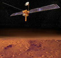 This
mission, called MRO for short, is an orbiter to study the martian surface.
The primary objectives are to study the weather and climate of Mars and
to help identify landing sites for future missions. Besides a visual
imager with a resolution better than one meter (three feet), the orbiter
will carry a spectrometer to analyze the surface composition. Provided
by the Italian Space Agency, a shallow subsurface sounding radar (SHARAD)
will be included to search for underground water. The orbiter will also
be closely tracked to give information on the gravity of Mars. This
mission, called MRO for short, is an orbiter to study the martian surface.
The primary objectives are to study the weather and climate of Mars and
to help identify landing sites for future missions. Besides a visual
imager with a resolution better than one meter (three feet), the orbiter
will carry a spectrometer to analyze the surface composition. Provided
by the Italian Space Agency, a shallow subsurface sounding radar (SHARAD)
will be included to search for underground water. The orbiter will also
be closely tracked to give information on the gravity of Mars.
MRO was launched on August 12, 2005, at 11:43 UT (7:43
A.M. EDT) from the Kennedy Space Center. It fired its main rockets on
August 30, 2005, for a main course correction, and the rockets will not
be used again until it reaches Mars. It will reach Mars on March 10,
2006, and it will spend six months aerobraking to reach an eventual polar
orbit of 255x320 km (160x200 miles). The planned science mission will
last approximately one martian year (687 days), from November 2006 through
November 2008.
After it's main mission, the orbiter will serve as a
communications relay for future missions. This will be the first part
of an "interplanetary internet" to be used for communications
back and forth between Earth and Mars to be used by international spacecraft.
The mission will also test an experimental optical navigation camera
that will serve as a high-precision interplanetary "lighthouse" to
guide incoming spacecraft nearing Mars.
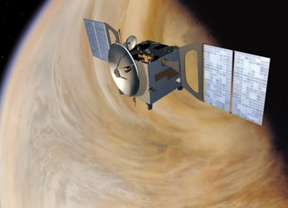
This mission owes its existence to the ESA Mars
Express mission. The ESA wanted to reuse the design of Mars Express
as well as have it ready to launch in 2005. Out of all the proposals,
Venus Express was chosen in 2002 because it would make use of the spare
instruments developed for Mars Express and Rosetta to achieve the main
science objectives - studying the atmosphere in detail.
This will be the ESA's first mission to Venus, with
the USA and Russia being the only two countries / space programs to have
sent craft to Venus. This probe will be the first craft to perform a
global investigation of the Venusian atmosphere. It will also be the
first craft to study Venus' surface using the recently discovered "visibility
windows" in the infrared part of the spectrum.
Venus Express was launched on a Soyuz-Fregat launcher
from Baikonur Cosmodrome in Kazakhstan on Wednesday, October 26, 2005,
at 06:33 CEST (04:33 GMT, 10:33 local time). Its journey to Venus will
last 153 days, when it will be captured by Venus' gravity in April 2006,
and take five days to achieve its planned elliptical orbit of 250x66,000
km (155x41,000 miles). The mapping mission should last for about two
Venus days (~500 Earth days), and it may be extended depending upon the
craft's health.
The 1240 kg mass spacecraft was developed for ESA by
a European industrial team led by EADS Astrium with 25 main contractors
spread across 14 countries. Initial Fregat upper-stage ignition took
place 9 minutes into the flight, maneuvering the spacecraft into a low-earth
parking orbit. A second firing, 1 hour 22 minutes later, boosted the
spacecraft to pursue its interplanetary trajectory.
When making its closest approach, Venus Express will
face far tougher conditions than those encountered by Mars Express on
nearing the Red Planet. For while Venus's size is indeed similar to that
of the Earth, its mass is 7.6 times that of Mars, with gravitational
attraction to match. To resist this greater gravitational pull, the spacecraft
will have to ignite its main engine for 53 minutes in order to achieve
1.3 km/sec deceleration and place itself into a highly elliptical orbit
around the planet. Most of its 570 kg of propellant will be used for
this maneuver.
Though the craft is used from many of the spare components
of Mars Express, Venusian environmental conditions are very different
to those encountered around Mars. Solar flux is four times higher and
it has been necessary to adapt the spacecraft design to this hotter environment,
notably by entirely redesigning the thermal insulation. Whereas Mars
Express sought to retain heat to enable its electronics to function properly,
Venus Express will in contrast be aiming for maximum heat dissipation
in order to stay cool.
To accomplish its science studies, it has seven instruments
onboard: Three are flight-spare units of instruments already flown on
Mars Express, two are from comet-chaser Rosetta and two were designed
specifically for this mission.
The PFS high-resolution spectrometer will measure atmospheric
temperature and composition at varying altitudes. It will also measure
surface temperature and search for signs of current volcanic activity.
The SPICAV/SOIR infrared & ultraviolet spectrometer and the VeRa
instrument will also probe the atmosphere, observing stellar occultation
and detecting radio signals; the former will in particular seek to detect
molecules of water, oxygen and sulphuric compounds thought to be present
in the atmosphere. The Virtis spectrometer will map the various layers
of the atmosphere and conduct multi-wavelength cloud observation in order
to provide images of atmospheric dynamics.
Assisted by a magnetometer, the ASPERA 4 instrument
will analyze interaction between the upper atmosphere and the solar wind
in the absence of magnetospheric protection such as that surrounding
the Earth (for Venus had no magnetic field). It will analyze the plasma
generated by such interaction, while the magnetometer will study the
magnetic field generated by the plasma.
The VMC camera will monitor the planet in four wavelengths,
notably exploiting one of the "infrared windows" revealed in
1990 by the Galileo spacecraft (when
flying by Venus en route for Jupiter), making
it possible to penetrate cloud cover through to the surface. The camera
will also be used to monitor atmospheric dynamics, notably to observe
the double atmospheric vortex at the poles, the origin of which still
remains a mystery.
|