|
|
|
Mars Global Surveyor (1996-present) Pioneer | Mariner | Viking | Voyager | Magellan | Pathfinder | Galileo | Mars Global Surveyor
Overview The Mars Global Surveyor (MGS) was designed to orbit Mars over a two year period and collect data on the surface morphology, topography, composition, gravity, atmospheric dynamics, and magnetic field. This data will be used to investigate the surface processes, geology, distribution of material, internal properties, evolution of the magnetic field, and the weather and climate of Mars. The craft arrived in 1997, began its primary mission in 1999, and has since spent over four years (over twice its initial planned mission) gathering useful scientific data. The MGS mission cost about $154 million to develop and build and $65 million to launch. Mission operations and data analysis cost approximately $20 million/year. MGS Camera images are available online at http://www.msss.com/moc_gallery/. Current Exploration Launched on November 7, 1996, at 17:00:50 UT, the Mars Global Surveyor (MGS) is currently orbiting Mars, having arrived after a 10-month cruise on September 12, 1997. The craft was inserted into an elliptical orbit at 01:17 UT, and spent the next four months in aerobraking maneuvers - using the planet's atmosphere to slow the craft - to lower its orbit into the final circular mapping orbit. Unfortunately, one of the solar panels failed to latch properly when it was deployed, and it later showed "unexpected motion" during the aerobraking - this is thought to be due to the fracture of a damper arm and subsequent structural damage. As a result, aerobraking was suspended for three weeks, at which time NASA adopted a new aerobraking program on November 7, 1997, which involved slower braking by dipping more shallowly into the Martian atmosphere in order to place less pressure on the solar panel to prevent it from breaking off or being damaged. This extended the aerobraking through April 1998, at which time a 11.6 hour science phasing orbit with a 171 km periapsis was achieved and aerobraking was halted. Five months later, aerobraking was resumed on September 23, 1998. Science observations were made periodically during the maneuvers. Finally, MGS reached its circular orbit in February 1999. It circles the planet in a 118 minute polar science mapping orbit with an index altitude of 378 km. The orbit is sun-synchronous and maps over the 2 P.M. crossing from South to North (the opposite as had been planned). The orbit has a seven-day near-repeat cycle so that Mars can be mapped in 26-day cycles. Science mapping began in mid-March 1999 (summer in the northern Martian hemisphere). The primary mission lasted one Martian year (687 Earth days) - through January 2001. An extended mission lasted until April 2002. In January 2003, the MGS turned into a support craft for other Martian missions (e.g. the 2001 Mars Odyssey). With sophisticated laser equipment, MGS has mapped Mars. It bounces a beam of laser light off Mars at a rate of ten per second, and then it records how long it takes the light to return to the craft. This works like sonar that ships use to map the ocean floor on Earth.
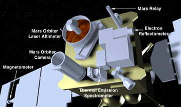
Another discovery (data taken October 1997, analyzed in early March 1998) is that above 50° latitude (about the upper half of the northern hemisphere), Mars is practically flat, with no hills or valleys. This is leading scientists to theorize that oceans may have flattened it, for the only areas on Earth that are this flat are at the bottoms of deep oceans. If this is true, further mapping may reveal a shoreline. Craft The spacecraft itself is a rectangular box approximately 1.17x1.17x1.7 m in size, made up of two parts - the equipment module and the propulsion module. All instruments except the magnetometer are stored on the nadir equipment deck on one of the 1.17x1.17 m surfaces. This is the top of the equipment module, which is 0.735 m high. The main thruster and propulsion tanks are on the opposite side from the instruments - on the propulsion module - which is approximately 1 m high. Two solar panels, each 3.5x1.9 m in size, extend out from opposite sides of the craft. A 1.5 m diameter parabolic high gain dish antenna is mounted on an adjacent side, and attached to a 2 m boom, which is extended for mapping operations so the antenna is held away from the body of the craft. The spacecraft is three-axis stabilized with no scan platform. The main 596 N thruster uses hydrazine and N2O4 propellant. Control is through 12 4.45 N hydrazine thrusters, mounted in four groups of three (two aft facing and one roll control thruster). The initial propellant load was 216.5 kg of hydrazine and 144 kg of N2O4. Four solar array panels (2 GaAs, 2 SI) provide 980 W of power to the spacecraft. Energy is stored in two 20 A-hr nickel hydrogen batteries, and supplied at 28 V DC. Temperature control is primarily passive with multilayer insulation, thermal radiators, and louvers, augmented by electrical heaters. Communications is achieved via the deep space network using the high gain antenna and two low gain antennas - one mounted on the high gain antenna and one on the equipment module. Uplink is in the X-band, downlink in the X and Ka bands. Minimum downlink rate is 21.33 kbps, 2 kbps engineering data downlink, and 10 bps emergency downlink. The instruments on the nadir equipment deck consist of a camera, thermal emission spectrometer, laser altimeter, and a radio transmission relay. A magnetometer/electron reflectometer sensor is attached to the end of each solar array, and an ultra-stable oscillator is used for tracking and gravity determination. An 8086 processor is used for the payload data subsystem, and 1750A processors for the standard controls processor and the engineering data formatter. Data is stored on four 0.75 Gb solid state recorders. Experiments Summary Mars Orbiter Camera (MOC) The MOC experiment is designed to obtain images of the surface and atmosphere of Mars for studying the meteorology/climatology and geology. Its primary objectives are to:
The MOC is the flight spare for the Mars Observer Camera, and hence it is essentially identical. In order to acquire images to satisfy these three objectives, the MOC consists of a narrow-angle assembly and a wide-angle assembly. These two assemblies are contained within a single cylindrical structure, approximately 80 cm in length and 40 cm in diameter. The narrow-angle assembly, which comprises the principal part of the instrument, is a 35 cm aperture, 3.5 m focal length (f/10) Ritchey-Chretien telescope with a 0.4° field of view, filtered to operate in a bandpass from 500-900 nm. The focal plane contains two 2048 element, 13 µm pixel CCD line arrays. This system is capable of providing an image resolution of 1.41 m/pixel at a nominal altitude of 380 km with an expected resolution of better than 1.5 m/pixel during the course of the mission. The wide-angle assembly consists of two cameras mounted on the side of the narrow-angle assembly. One wide-angle camera, optimized to operate in a band pass from 400-450 nm (blue) has a focal length of 11.4 mm (f/6.3). The other, designed to operate in a band pass from 575-625 nm (red), has a focal length of 11.0 mm (f/6.4). The wide angle instruments have fields of view of 140°, with resolution of 280 m/pixel at nadir and 2 km/pixel at the limb. The focal plane contains two 3456 element, 7 µm pixel CCD line arrays. All three cameras are mounted in a fixed position on the nadir panel so that, during the mapping portion of the mission, they are always pointed toward Mars. The electronics for the MOC are completely redundant and the narrow-angle and wide-angle cameras can be operated by either set of electronics and all three cameras can be operated simultaneously. The camera is controlled by a 32-bit (10 MHz, 1 MIPS) SA3300 microprocessor with four ASICs, 128 kb EPROM, and 192 kb SRAM. Because of the high volume of data which imaging experiments can generate, the MOC electronics contain not only a large amount of memory (~12 MB DRAM buffer) for processing and storing the images, but also have the capability of utilizing a number of data compression techniques (both lossless and lossy). Further, the MOC can transfer these data (either to the on-board recording system or via real-time transmission) at any rate of which the spacecraft is capable. As a result, the equivalent of two, four, or eight (depending on mission phase) 2048x2048 pixel images can be processed on record-only days and, once every three days on average, 14 such images can be processed and sent during an eight-hour real-time pass. In-flight calibration of the MOC is extremely limited due to the fixed pointing of the instrument. Some opportunities for in-flight calibration are possible during regional or global dust storms. Otherwise, pre-flight measurements made to characterize the instrument performance comprised the bulk of the instrument calibrations. Available data rates are 700, 2856, 9120, and 29260 real-time bits/sec. Finally, due to the MOC's large capacity for the storage and processing of images, it is intended to be used as part of the Mars Relay, which will provide a communications link between other Mars missions and the Earth. Thermal Emission Spectrometer (TES) TES is designed to measure the infrared thermal radiation emitted by the Martian atmosphere and surface. This information will be used to study:
This information will extend and improve upon measurements of thermal infrared emission instruments carried by earlier missions (Mariners 6, 7, and 9 and Vikings 1 and 2). The TES instrument encompasses three measurement channels: A spectrometer, a bolometer or radiance channel, and a reflectance or albedo channel. The spectrometer is a Michelson interferometer with six fields of view, each with 3 km resolution. The spectrometer measures 143 distinct spectral bands covering a range of 6.25 to 50 µm at spectral resolutions of 5 and 10 per cm. The bolometer (radiance) channel measures broadband thermal infrared radiance from 4.5 to 100 µm with a spatial resolution of 3 km. The albedo (reflectance) channel measures broadband visible/near-infrared solar reflectance from 0.3 to 2.7 µm, also at 3 km resolution. The detectors are three sets of 2x3 pyroelectric arrays with a pixel size of 8.3 mrad, giving fields of view of 24.9x16.6 mrad. The TES is run by an 80C86 microprocessor and a TI digital signal processor (FFT). It contains 0.6 Mb RAM for operations and buffering. The available data rates are 688, 1664, and 4992 real-time bits/sec. It can accept commands at approximately 300 words/day as multiple 16 bit words. The peak transient power requirement is 18.2 W. The TES is fixed to one side of the MGS spacecraft along with the other instruments, and it points directly down towards the surface. A mirror allows views of deep space, nadir, and aft and forward limbs. Mars Orbiter Laser Altimeter (MOLA) The MOLA is designed to map the Martian global topography and can also be used to measure the height of water and carbon dioxide clouds. This information will be used for scientific objectives that include study of the surface processes on Mars including the formation and evolution of volcanoes, basins, channels and the polar ice caps. Also, combined with gravity and other data, one can study the structure and evolution of the interior of Mars, including the lithospheric thickness and strength, internal convection, composition, thermal history, and release of water and carbon dioxide to the surface. MOLA data can be used to calculate the volume and seasonal changes in the polar ice deposits, and to measure the altitude and distribution of water and carbon dioxide clouds, for the purpose of constraining the volatile budget in the Martian atmosphere. The MOLA works by transmitting a laser pulse down towards the surface. The pulse is reflected off the surface (or cloud) back to the instrument, where the return is detected. The two-way travel time is recorded, giving a measure of the distance between the spacecraft and the surface. Corrections are made to this distance based on atmospheric effects, and accurate tracking of the spacecraft position allows an estimate of the surface altitude or cloud height. A large number of surface altimetry measurements will be taken and combined to produce a global topographic map. The MOLA consists of a diode pumped, Q-switched Nd:YAG laser transmitter with a pulse energy of 40-45 mJ. It can send continuous bursts of 10 pulses/sec, each pulse having a beam diameter of 1 cm and a divergence of 0.45 mrad. The receiver is a 50 cm parabolic antenna with a Si APD detector and four electronic filters (20, 60, 180, and 540 ns). The receiver field of view is 0.85 mrad with a 10° cone about the mirror exclusion. The vertical resolution is 2 m local (relative) and 30 m global (absolute). The horizontal resolution is 160 m. The altimeter is run by a 80C86 microprocessor with 54HC family logic. The altimeter is mounted to the MGS instrument panel. Radio Science Investigations (RS) The RS have two distinct objectives; the first is to map the planet's gravitational field and the second is to measure the atmospheric pressure and temperature in the polar regions. The gravity field results, combined with topographic data from the MOLA experiment, will allow estimates to be made of the structure of the Martian interior from which studies can be done of the thermal and chemical evolution of the planet and the history of surface features and the atmosphere. The atmospheric experiment will aid in studies of atmospheric dynamics and meteorology and in detailed studies of transport of water, dust, and carbon dioxide in the atmosphere. The gravity experiment is consists of measuring the Doppler shift in radio waves transmitted from the spacecraft to Earth. This gives the velocity of the spacecraft along a line-of-sight (LOS) from Earth. Changes in this velocity give LOS accelerations, which after processing can be interpreted as spatial anomalies in the gravitational field of Mars. Over many orbits a map of the planet's gravitational anomalies can be built up, which can be interpreted in terms of the distribution of mass anomalies on the planetary surface and in its interior. The radio occultation experiment operates when MGS is disappearing behind Mars or reappearing as seen from Earth. At this time, the radio waves transmitted from the spacecraft pass through the Martian atmosphere on their way to Earth. The atmosphere affects the signal, and measuring the resultant effects allows properties of the atmosphere to be studied. Because of the polar orbit of the spacecraft, these measurements can only be made near the poles. The radio science instrument consists of an ultrastable oscillator and the normal MGS transmitter and receiver. The oscillator provides a frequency reference for the radio science experiments. It operates on frequencies of 7164.624 MHz uplink, 8417.716 MHz downlink (closed loop) and 8416.368 MHz downlink (in-use mode). The oscillator has stabilities (square root of the Allan variance) of 5x10^-12 for 0.1 s integration, 1 x 10-12 for 1.0 sec integration, and 4x10-13 for 10 to 1000 sec integration. A high accuracy clock generator ensures precise frequencies. In warm-up mode, the oscillator draws 4.5 W. Magnetometer / Electron Reflectometer (MAG/ER) The MAG/ER experiment is designed to establish the nature of the magnetic field of Mars, develop appropriate models for its representation, and map the Martian crustal remnant field to a resolution consistent with the MGS orbital altitude and ground track separation. The presence and nature of a magnetic field on Mars will provide evidence of a liquid core, which will in turn constrain models of the internal composition, evolution, and dynamics. The experiment consists of two separate subsystems - the magnetometer (MAG) and the electron reflectometer (ER). The instruments are mounted on a boom extending from the spacecraft body. The magnetometer subsystem consists of two triaxial fluxgate magnetometers. The dual magnetometer technique, similar to instruments developed for other missions (e.g. Voyager and Magsat), allowed the real-time estimation of the spacecraft-generated magnetic field and provided redundancy for the in situ magnetic field measurements. Each magnetometer makes measurements in three orthogonal directions over the range ±16 nT to ±65,536 nT, over 7 ranges, varying by a factor of 4. The data are measured at 12 bits/sample. The ER is a symmetrical quadspherical electrostatic analyzer with a field of view of 360° by 14°. The ER can measure 1 eV to 10 keV with a resolution ΔE/E of 0.25. The electronics consist of a 80C86 microprocessor with a 16 kb memory. The instrument can measure from 2 to 16 magnetic vectors per sec. Available data rates are 324, 648, and 1296 bits/sec. Mars Relay Communications Experiment The MGS Mars Relay is a communications link between Earth, other orbiting spacecraft, and various Mars surface lander and rover missions being planned by the U.S., Europeans, and Russians. It will allow high speed reliable communications to and from these surface instruments, without requiring them to have the capability of transmitting directly to Earth. The Mars Relay consists of a 86 cm high, 2.5 kg quadrifilar helix fiberglass antenna mast mounted on the spacecraft and an electronics box and coaxial cable. The system receives data from the surface missions and routes them for storage to the large on-board storage memory buffer of the Mars Observer Camera (MOC). The stored transmissions are then routed to Earth via the MOC. The transmission frequency to the Mars ground stations is 437.1 MHz at 1.3 W. The receive frequencies (from the stations) are 401.5 and 405.6 MHz. The antenna field of view ranges from limb to limb. Accelerometer The MGS spacecraft carries an accelerometer designed to measure the change in velocity as the spacecraft performed aerobraking maneuvers in the Martian thermosphere. The accelerometer data can be used to deduce atmospheric drag on the spacecraft so that atmospheric densities can be estimated. The z-axis accelerometer is aligned closely to the spacecraft velocity vector. It has a sensitivity of 0.332 mm/s per count, allowing measurements up to at least 170 km altitude. A typical set of accelerometer measurements during aerobraking spanned from about 200 sec before periapsis to 200 sec after periapsis, about 30° of latitude. Additional measurements obtained before and after this period are used to determine accelerometer bias for each pass. Measurements are obtained every 0.1 sec. Accelerations of 1 µg were detected. Craft Data
|
|||||||||||||||||||||||||||||||||||||||||||||||||||||||||||||||||||||||

 One
discovery (early October 1997) is that Mars has over eight "magnetic patches" that
might be the remnants of an ancient magnetic field. The patches' axes, though,
are pointing in all different directions. The strongest field is only about 1.3%
that of Earth's magnetic field. The field fragments could have been formed when
iron-rich rocks rose at different times, and then became trapped in the surrounding
rocks. This model suggests that each field fragment is a picture of what Mars'
magnetic field looked like at various times.
One
discovery (early October 1997) is that Mars has over eight "magnetic patches" that
might be the remnants of an ancient magnetic field. The patches' axes, though,
are pointing in all different directions. The strongest field is only about 1.3%
that of Earth's magnetic field. The field fragments could have been formed when
iron-rich rocks rose at different times, and then became trapped in the surrounding
rocks. This model suggests that each field fragment is a picture of what Mars'
magnetic field looked like at various times.